Recently, I put together a demonstration object in OpenSCAD and QCad for a friend to impress people with.
His response, after I demonstrated how it was done, was “if this was a screencast, I would watch it”.
I don’t like screencasts, so I thought I’d write a tutorial.
The object itself is fairly useless, but looks cool and is easy to make. Hopefully this will make OpenSCAD a bit less scary.
You will need QCad and OpenSCAD installed, so do that first.
To get QCad for Windows, download it from sourceforge. OpenSCAD is at openscad.org.
Here is what the finished object looks like printed:
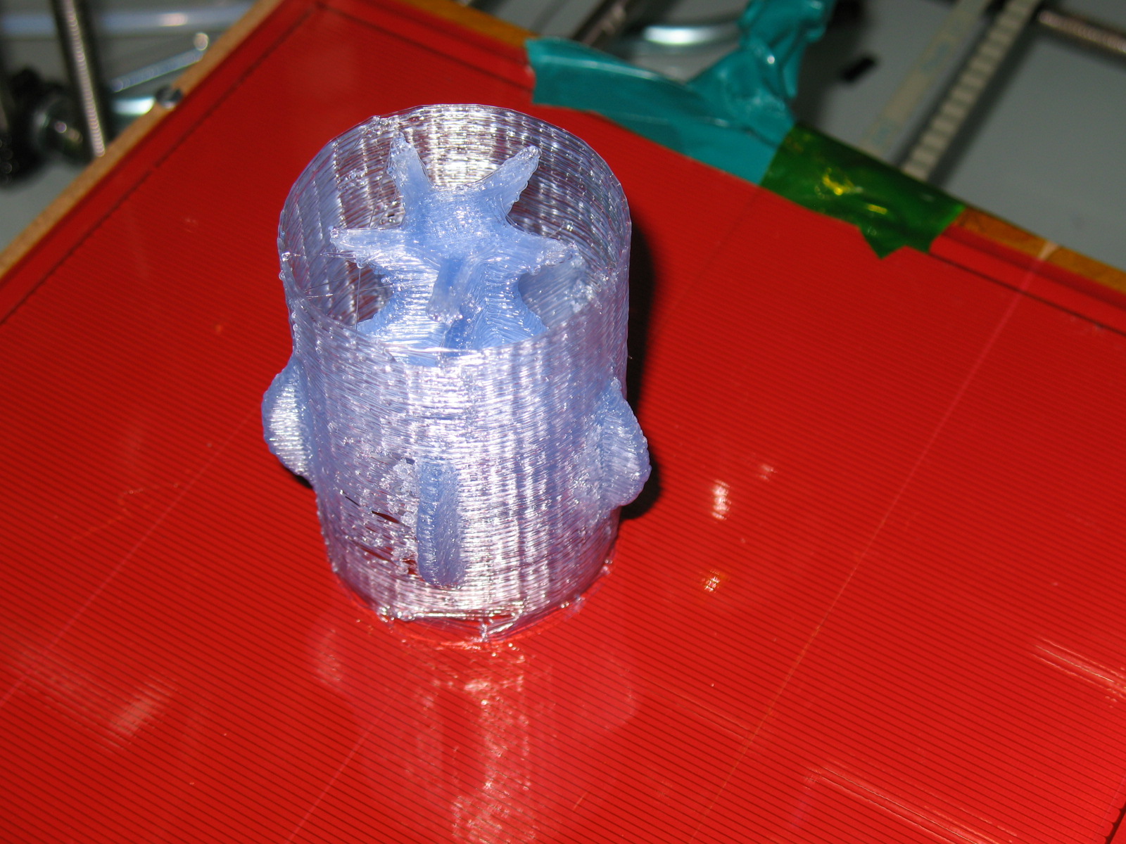
So let’s walk through the process of building it.
Open up QCad.
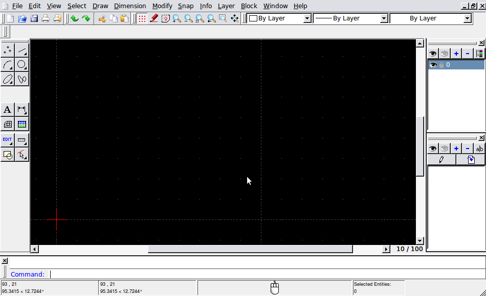
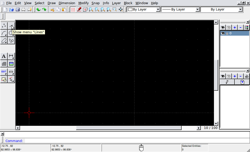
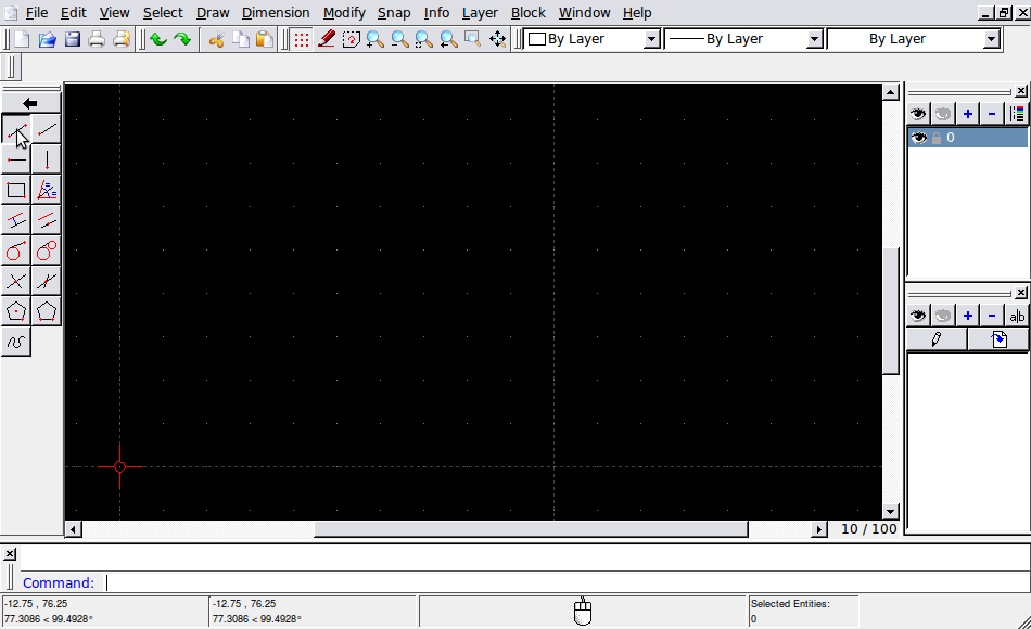
Click the “Line” button. This changes the toolbar to the line menu. The arrow at the top takes you back to the previous menu.
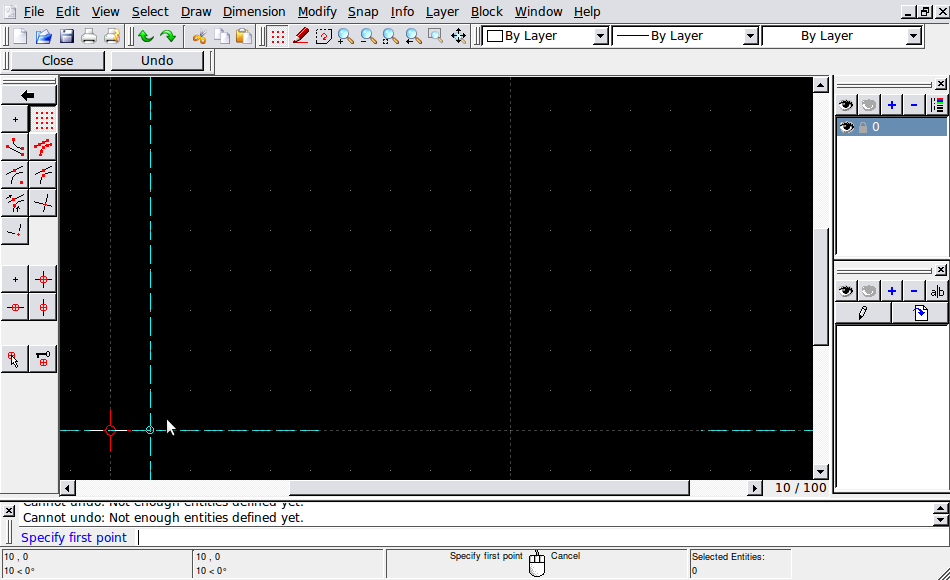
Click the first button, “Line with two points”. This changes the toolbar to the “snap to” menu.
Click “Snap to grid”. This makes sure that you can only select points that are on the grid.
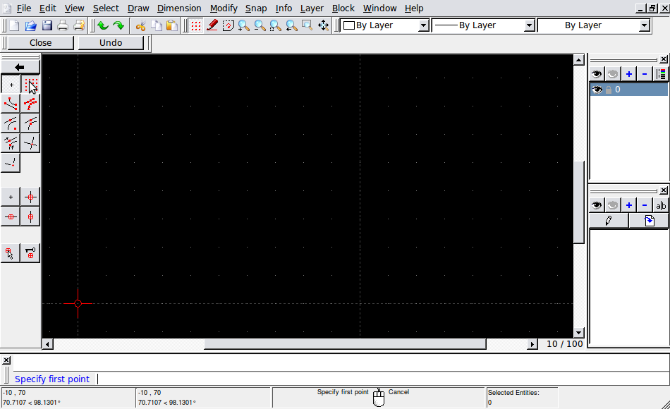
Try it out by moving the mouse pointer around in the empty drawing field. It will jump from grid point to grid point.
Now, position your cursor near the first grid point to the right of the red crosshair.
The display at the bottom of the window should read 10,0. This shows you the coordinates you are currently at.
Because you are in snap to grid mode, it will snap to the nearest grid point.
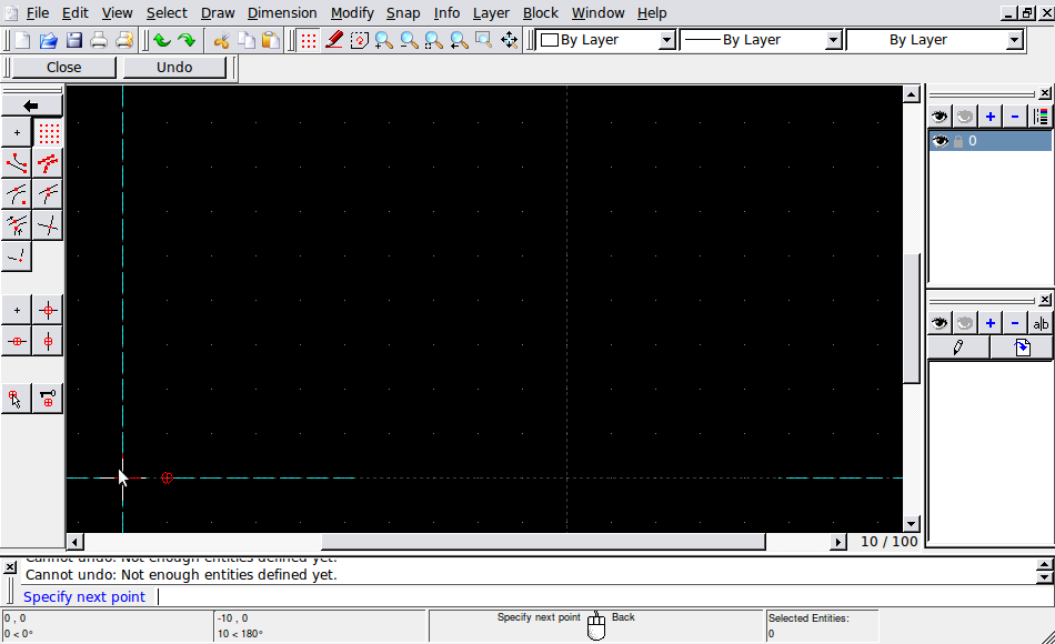
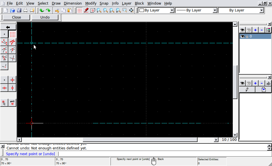
Click, then move the cursor until it snaps to 0,0 (the red crosshair). Click on that. This creates a line segment from 10,0 to 0,0.
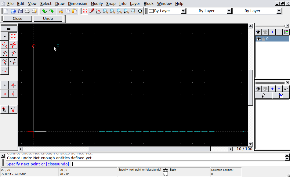
Move the cursor until it snaps to 0,70. Click on that to add a line segment.
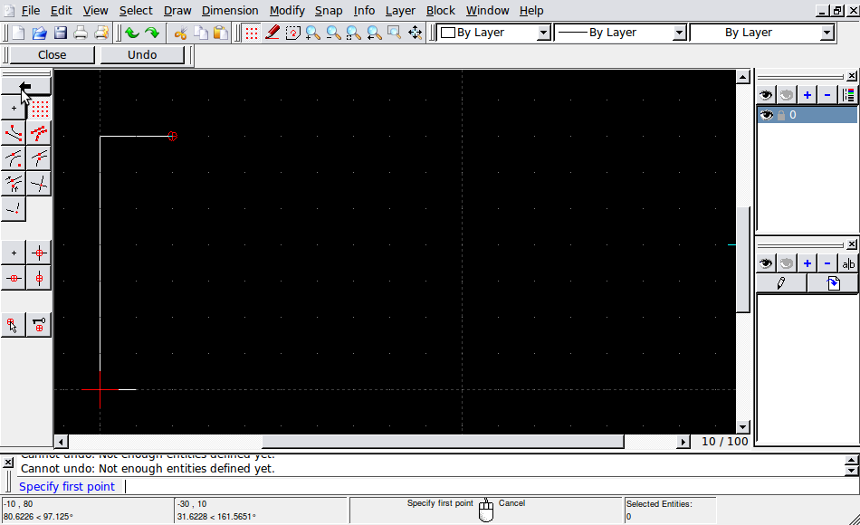
Move the cursor until it snaps to 20,70. Click to add the final line segment, then right-click to finish the line.
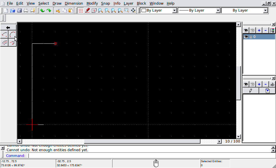
Click on the arrow at the top of the toolbar twice to go back to the main menu.
Click the “Arc” button.
Click the “Arc with three points” button.
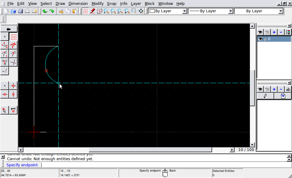
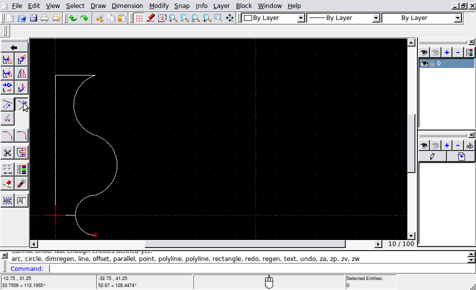
Click on the following points: 20,70; 10,50; 20,40. You now have an arc.
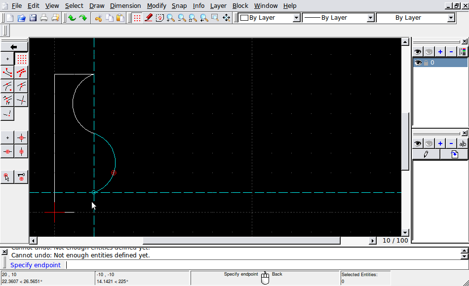
Make a second arc with points 20,40; 30,20; 20,10.
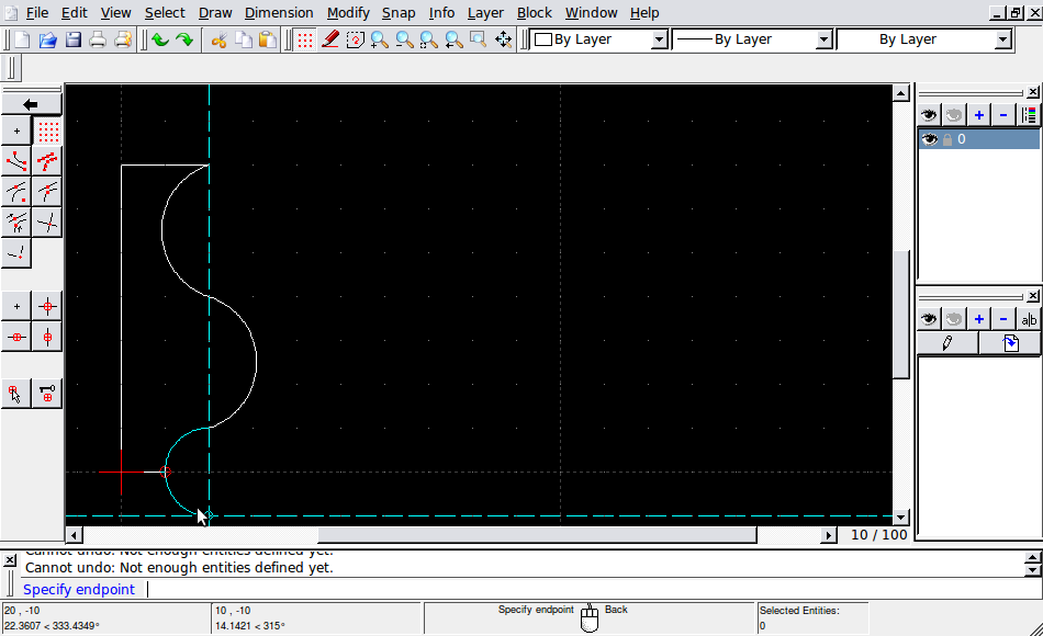
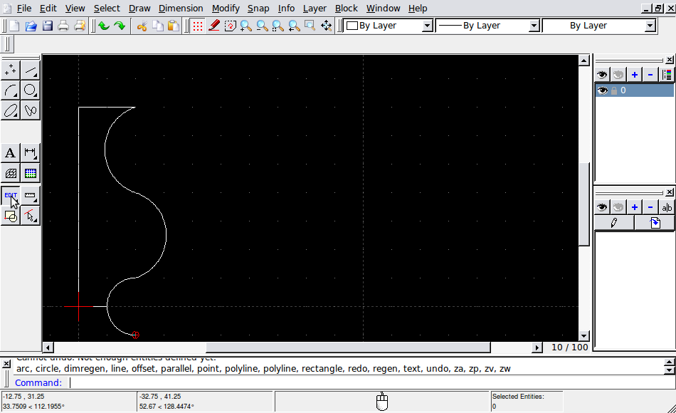
Make a third arc with points 20,10; 10,0; 20,-10. It will extend past the bottom line. Let’s fix that.
Go back to the main menu (click the arrow twice) and click the “Edit” button.
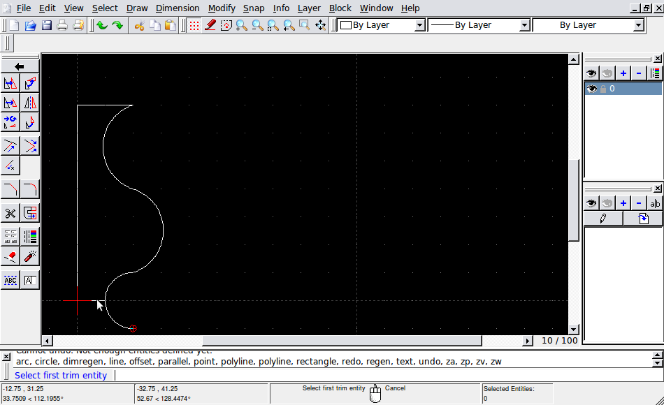
Click the “Trim/Extend two” button. This will make sure two lines do not extend beyond the point they meet at.
Click the first line.
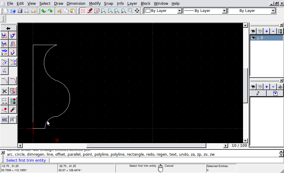
Click the last arc.
And we’re done.
Save the shape in any directory you like, and name the file “outline.dxf”. You can close QCad now.
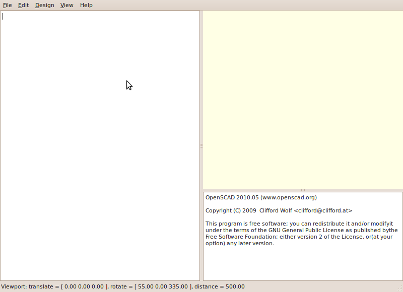
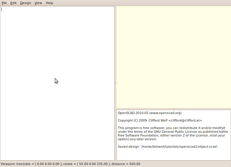
Now, start up OpenSCAD
Save the empty file it start with as “object.scad” in the same directory as outline.dxf.
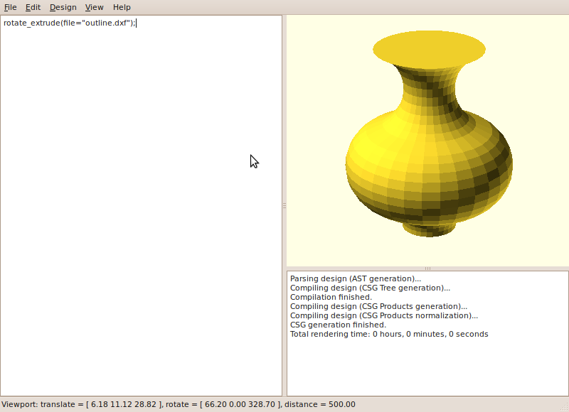
Okay, let’s load our outline and extrude it. We’ll use the OpenSCAD rotate_extrude function, which takes an outline and rotates it in a circle around the X=0 line, forming a solid object.
This requires that the outline is closed, which is why we had to trim the last arc in QCad.
Type in the following line:
rotate_extrude(file="outline.dxf");
note the quotes and the semicolon. These are important. Press F5 to see your work.
You can right-drag the window on the right to pan, and left-drag to rotate the camera.
Impressive, no? Okay, let’s try something different. Change the text so it looks like this:
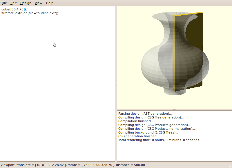
cube([30,4,70]);
%rotate_extrude(file="outline.dxf");
The % makes an object translucent, and removes that object when the model is rendered. Right now, we are just using it to
be able to see inside the object. Press F5 to see what happens.
The cube we added is inside the extruded object.
Now change the code to:
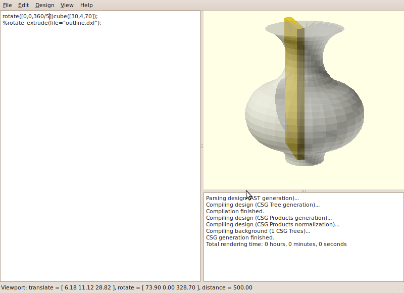
rotate([0,0,360/5])cube([30,4,70]);
%rotate_extrude(file="outline.dxf");
Again, press F5 to see the result. The cube has rotated around the Z (vertical) axis by 360/5=72 degrees.
Now, change it to say:
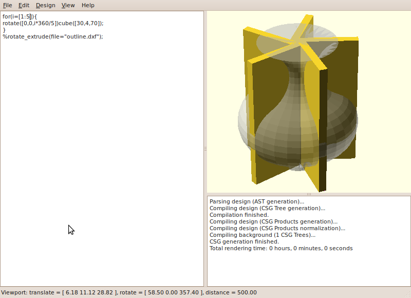
for(i=[1:5]){
rotate([0,0,i*360/5])cube([30,4,70]);
}
%rotate_extrude(file="outline.dxf");
This is a for-loop. It sets the value of i to 1, then 2, then 3 and so on up to 5, and executes the rotate-cube command once for each value.
So you have one cube rotated by 72*=72 degrees, one by 72*2=144 degrees, one by 72*3=216 degrees, and so on.
Note how the cubes are off center. That’s because the cube command makes a cube with one corner at 0,0,0 and the other corner at 30,4,70, so it is not centered on the Y axis.
To make the center of the cube be at 0,0,0, you can use cube([30,4,70],center=true);
Now, change the code to the following:
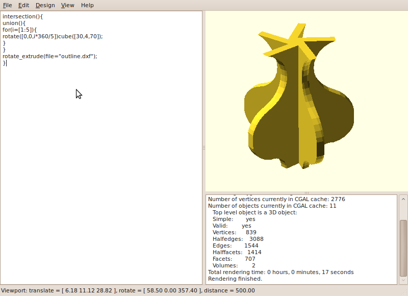
intersection(){
union(){
for(i=[1:5]){
rotate([0,0,i*360/5])cube([30,4,70]);
}
}
rotate_extrude(file="outline.dxf");
}
This time, press F6 to see the result. It will take a bit longer than before.
The union command combines everything within the curly brackets after it into one object.
The intersection command looks at two or more objects and generates a new object out of only the parts where the objects overlap.
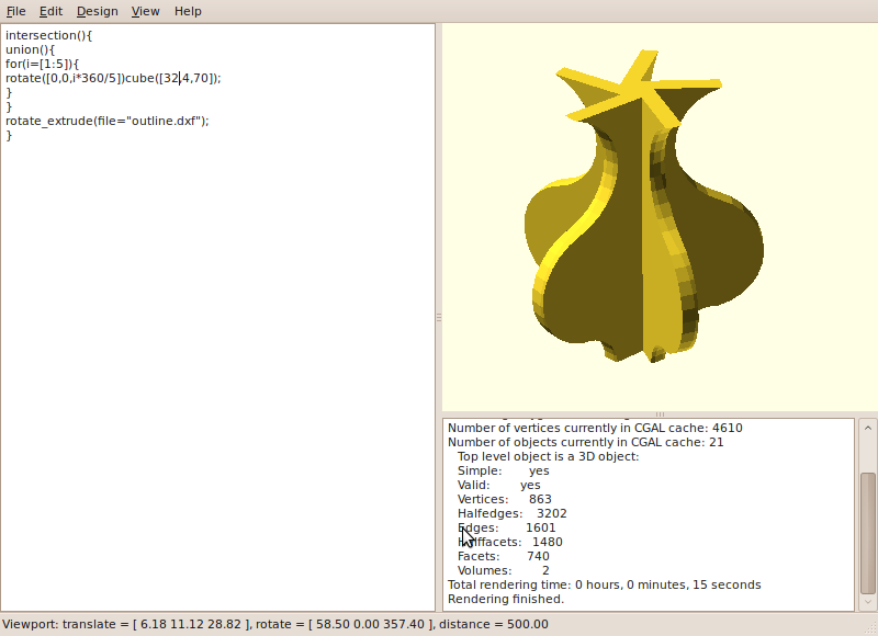
Interesting result, isn’t it? Note how the outer curve is cut off a little bit. Let’s fix that. Change the cube’s width to 32:
intersection(){
union(){
for(i=[1:5]){
rotate([0,0,i*360/5])cube([32,4,70]);
}
}
rotate_extrude(file="outline.dxf");
}
Again, hit F6 to see the result.
Nice and curvy this time.
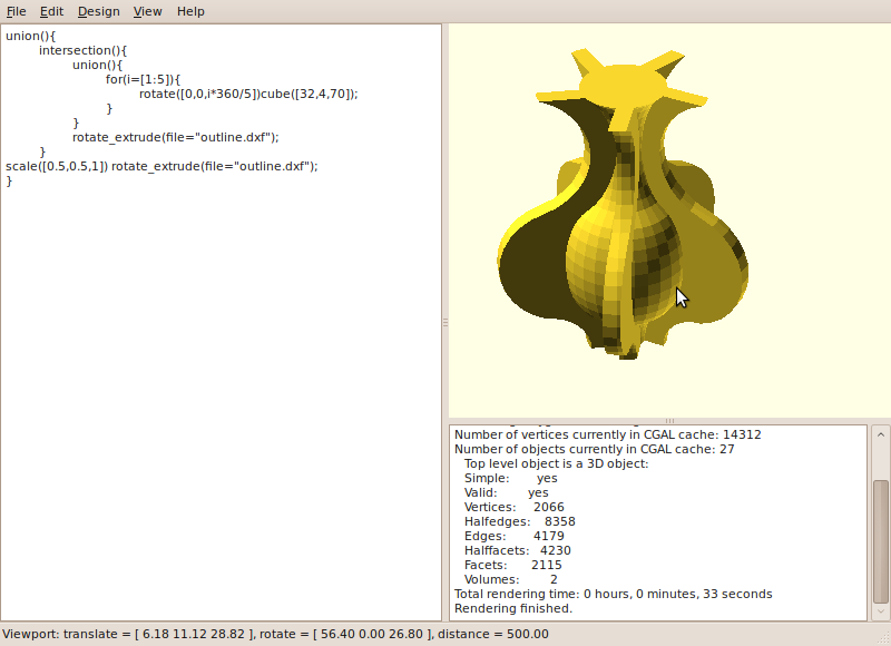
Let’s add some more curves. You can indent the file to make it more readable:
union(){
    intersection(){
        union(){
            for(i=[1:5]){
                rotate([0,0,i*360/5])cube([32,4,70]);
            }
        }
        rotate_extrude(file="outline.dxf");
    }
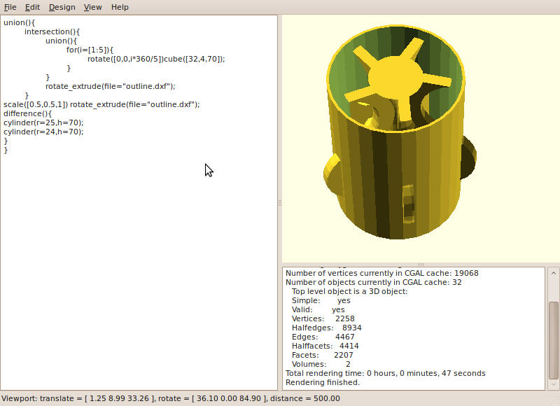
    scale([0.5,0.5,1]) rotate_extrude(file="outline.dxf");
}
Note how the new union command wraps everything we had so far. The scale command changes the size of an object.
Here, we scale the extruded shape by 0.5 in the X and Y dimensions, and by 1 in the Z dimension.
Hit F6 to see the result.
Let’s add a hollow cylinder. To do this, we subtract a smaller cylinder from a bigger one.
The difference command subtracts the second and following objects from the first object it is given:
union(){
    intersection(){
        union(){
            for(i=[1:5]){
                rotate([0,0,i*360/5])cube([32,4,70]);
            }
        }
        rotate_extrude(file="outline.dxf");
    }
    scale([0.5,0.5,1]) rotate_extrude(file="outline.dxf");
    difference(){
        cylinder(r=25,h=70);
        cylinder(r=24,h=70);
    }
}
Again, press F6 to see the result. Use the mouse to rotate the object and look at it from different angles.
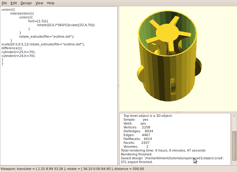
Save the object by pressing F2. Then, click on the “Design” menu and select “Export as STL…”. Name it “object.stl” or anything you like.
You now have an STL file you can use with Skeinforge, Repsnapper, or Reprap Host to print.
For more information on OpenSCAD, read through the OpenSCAD manual (it’s not very long).


I find this fascinating. The applications are endless and the loss is nill. No heat, no noise. I want my own beermug for carnaval!
Very nice tutorial.
You can even do the whole thing in OpenSCAD…
union(){
intersection(){
union(){
for(i=[1:5]){
rotate([0,0,i*360/5])cube([32,4,70]);
}
}
rotate_extrude()Vase();
}
scale([0.5,0.5,1])rotate_extrude()Vase();
difference(){
cylinder(r=25,h=70);
cylinder(r=24,h=75);
}
}
module Vase(){
difference(){
square(size =[20,70]);
translate([25,55])
circle(r=5*sqrt(10));
translate([20,0])
circle(r=10);
}
translate([15,25])
circle(r=5*sqrt(10));
}
Of course you can! But I wanted to show people some basic QCad stuff as well, since that looks way scarier at first glance than OpenSCAD does.
Thank you very much for this impressive tutorial! I am quite familiar with libreCAD / QCAD, but don’t know anything about OpenSCAD 😀