uRADMonitor campaign update 2

(This is a part 2 to my last campaign update post)

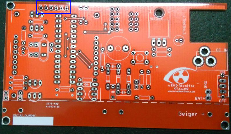
The KIT1 has arrived!

Assembled uRADMonitor KIT1.

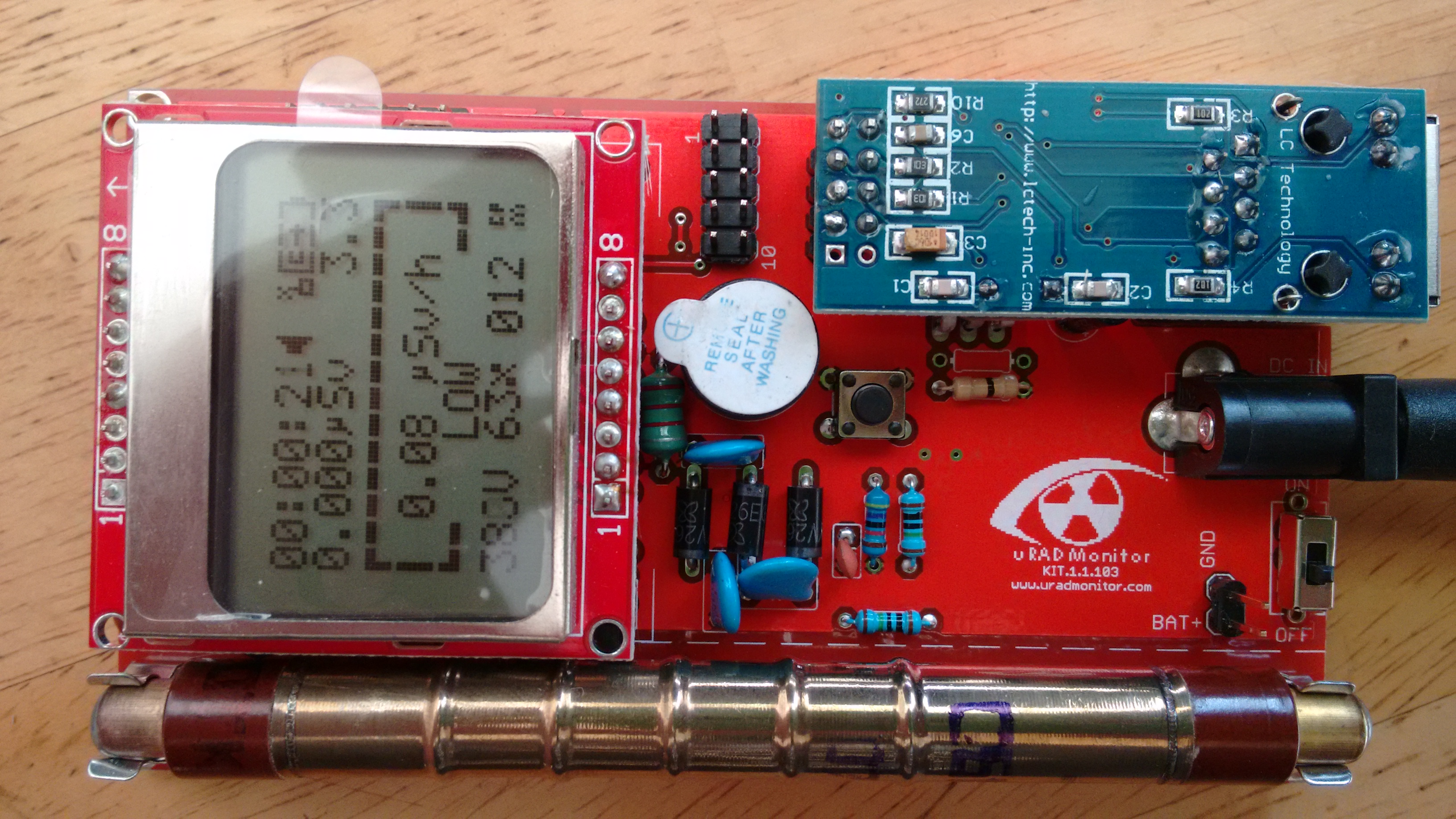
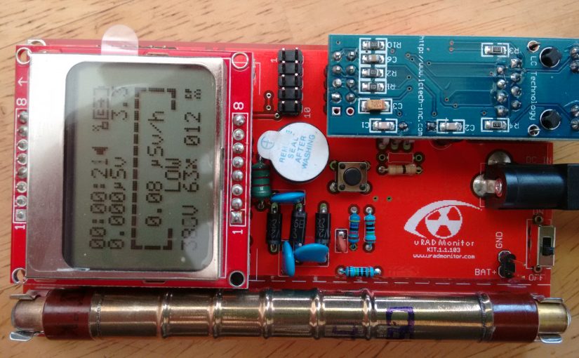
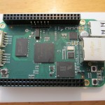
I could not help myself from soldering it immediately, and it worked! My new device is beeping along nicely, without any big trouble.

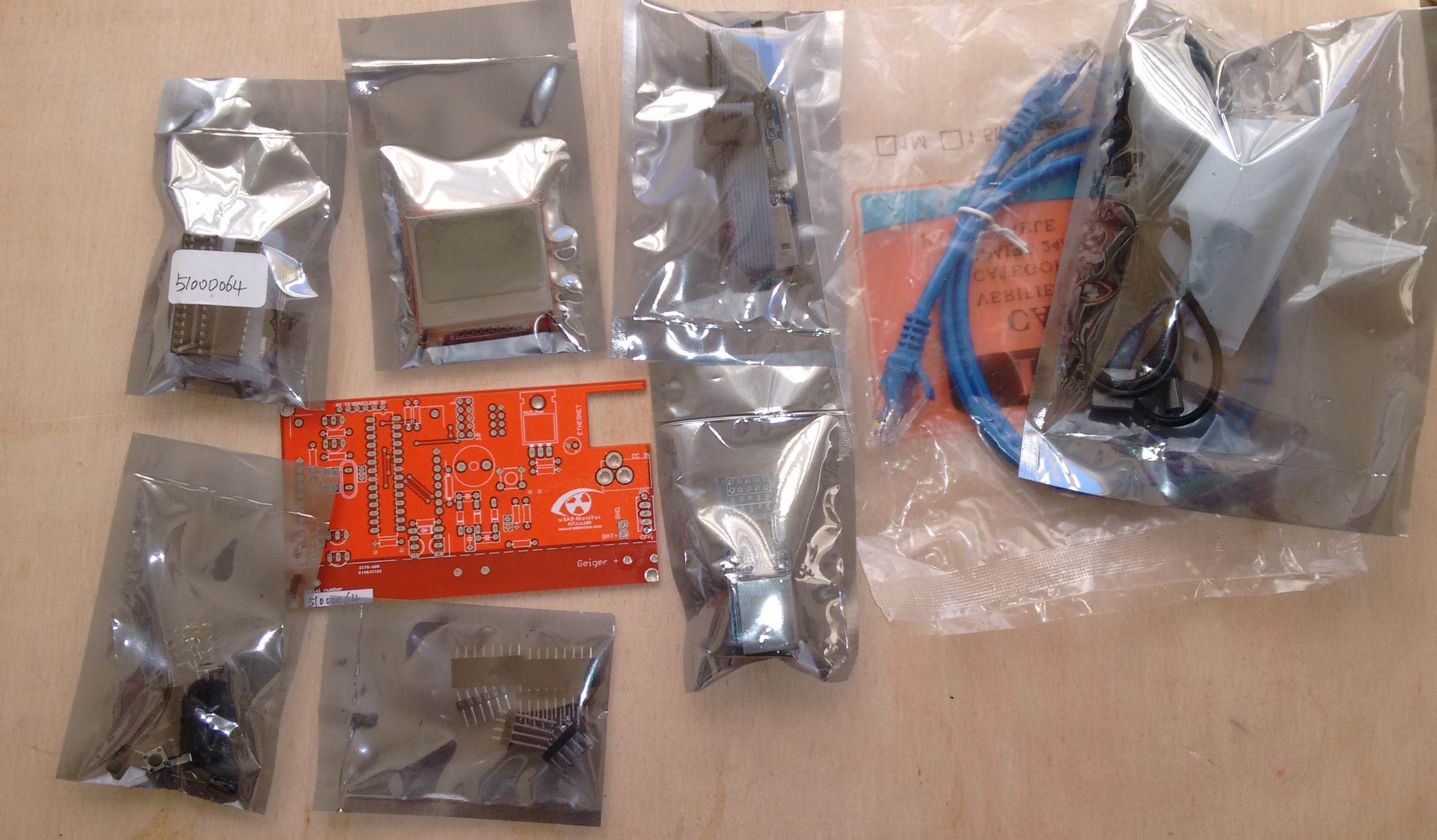
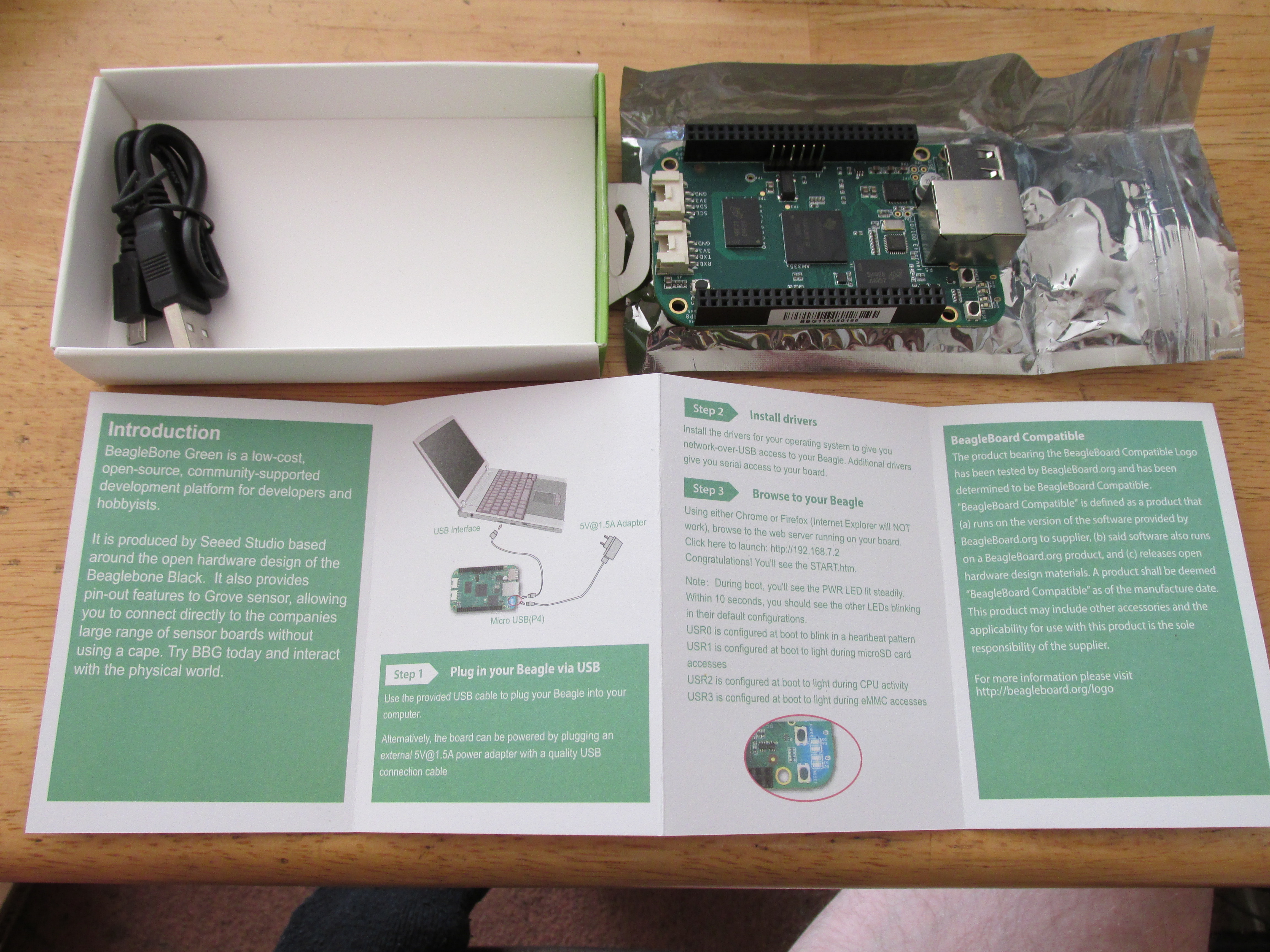
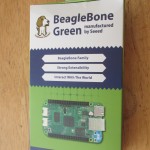
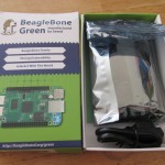
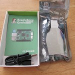
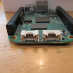
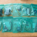
So what did I get? A small brown box, containing a lot of antistatic bags, and a manual. The manual is made in black on white, while there are some hints that it was printed on a full color printer. The links on page 9 are printed in blue πŸ˜›

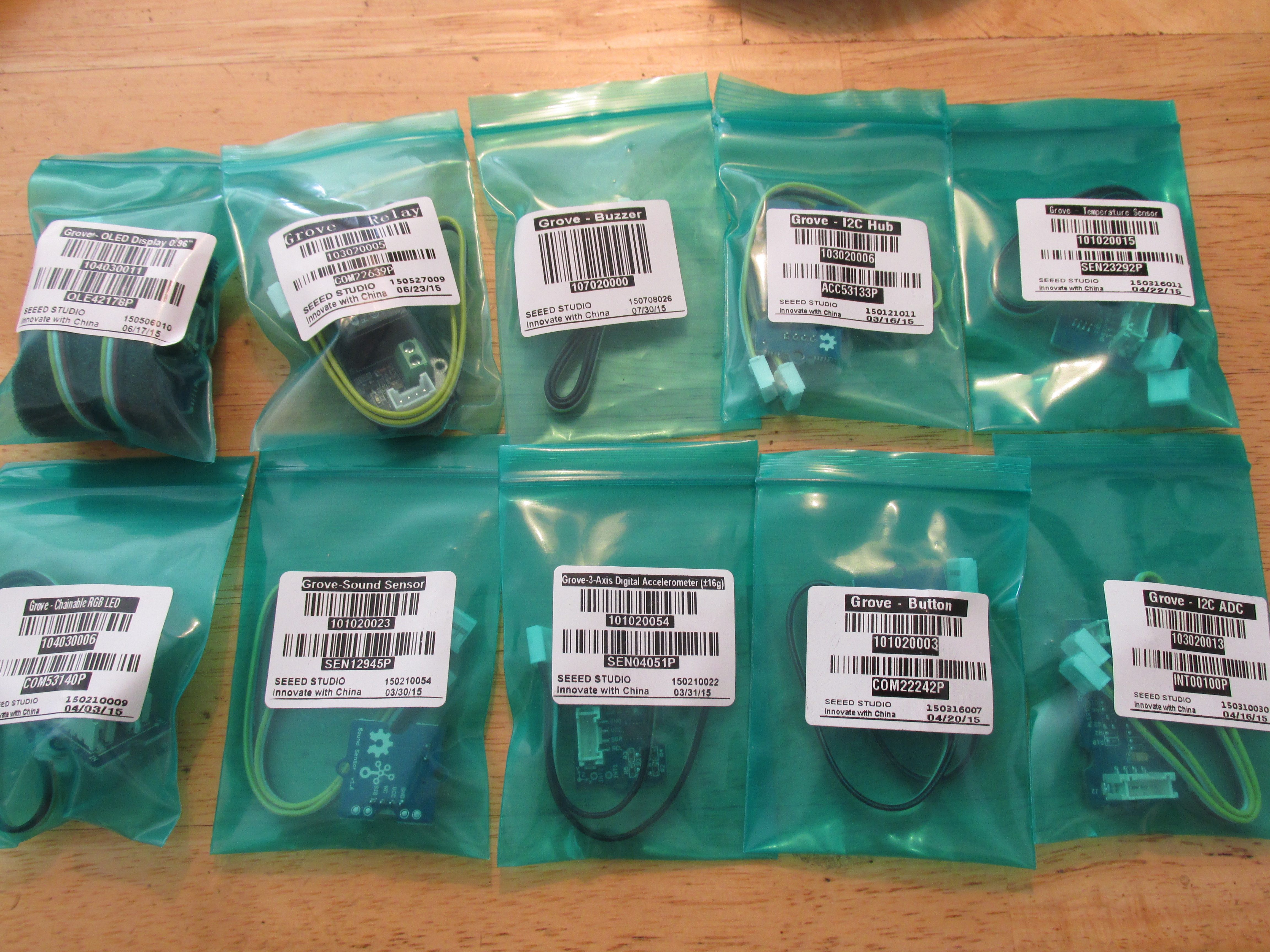
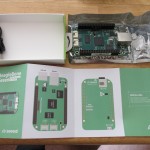
So on to the baggies: one containing the PCB, one with the SBM-20, one with a paper with most of the parts, one with the larger parts, one with the ATMega, the usbASP(v2 as per the manual), the screen, network breakout, and the two bags with the network card, and the usb power cable with a really small transformer, probably for USA use.

Most of the parts of the kit.

Soldering the parts was relatively easy, the only issues were due to my inexperience in soldering.

The small parts.
The small parts.

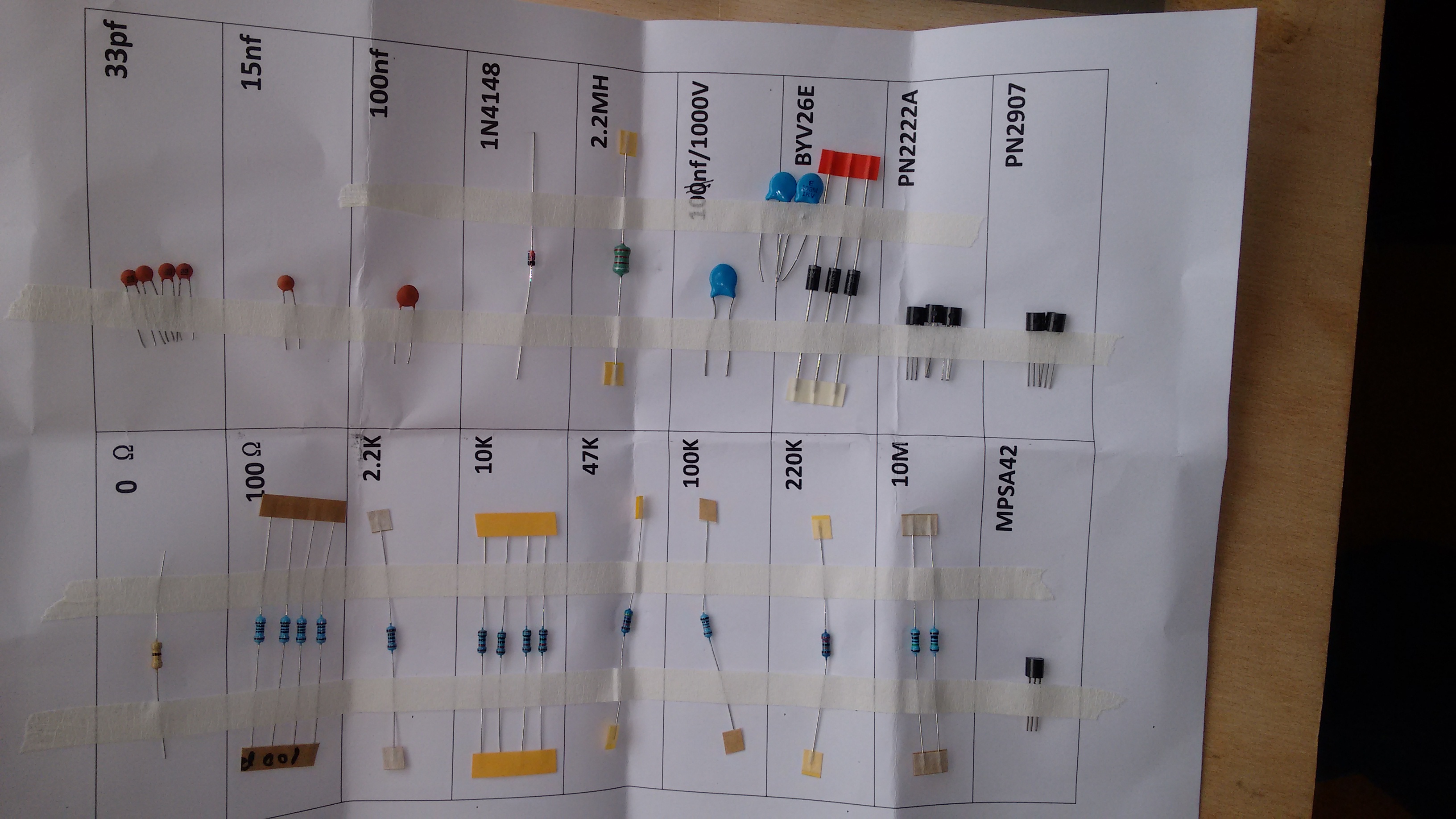
The silkscreen does not mention the parts, so at first I started writing a map of where parts are supposed to come, and what parts on the paper would get what designation. Strangely the PN2907’s weren’t mentioned on the list (p5), but they were the only ones, so I could fill in the blanks πŸ™‚

From there on I continued soldering the parts according to height, so I would do the flattest ones first. Working my way up, I anticipated not that much trouble, but noticed again how much harder through hole soldering is than surface mount, especially for beginners, thanks to the course I did with Kliment. Thanks again for the course!

In the end there was just one stupid mistake inΒ  re-seating the screen upside down before switching it on for the first time, but luckily it did not break. As I saw my mistake immediately, all went perfectly from then on.

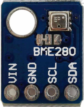
The BME280 is already setup, but there are some additions needed for it in theΒ  firmware. Radu told me he will add them himself, so when he adds them to the GitHub repo, the device can be reflashed and use the information from the added sensors. For this I will also need a file from Radu, to make sure my login to the central database stays secure. I am still using the device offline, as it will move a lot in the beginning, and it is not even close to its final destination. It would be very nice if I could connect the device to my own network only first, to not clutter the DB. For now I have no logging, and can only see the info on the device itself. I will investigate further. I have an Sparkfun OpenLog lying around, maybe that could do the trick for now, and maybe I could even add a GPS that way to make it fully mobile.

In other news, the BME680 did finally arrive. Thank you Bosch! Production on the model D will be able to continue as soon as the parts arrive at the factory.

Also a new fixed/mounted outdoor measurement device is announced, the model A3. This seems to be a model incorporating the same improvements as seen in the model D, but I have to look into it more closely to see what changed.

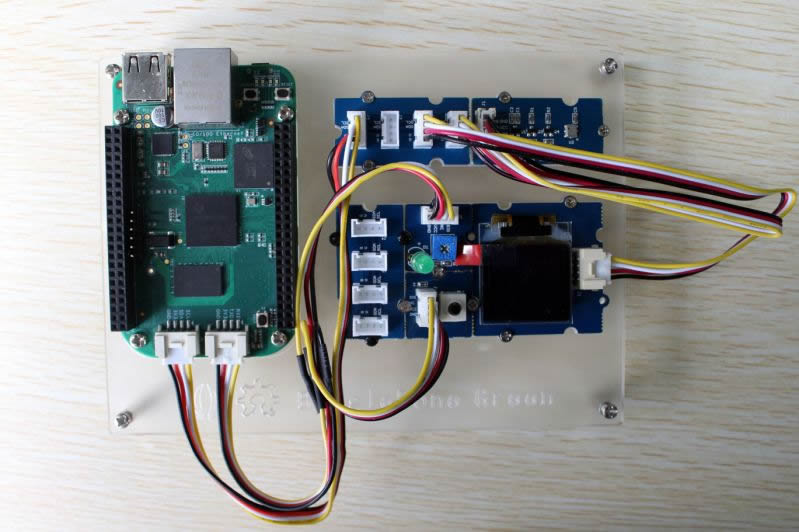
I just got a mail from Radu asking me to show pictures of my soldering. No winning entry from me, I dislike some joints, but here is the result πŸ™‚

KIT1 soldered (badly)

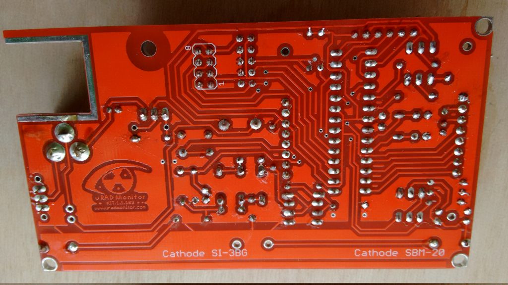
I will try to touch it up soon, and remove the flux, but it seems 18y whiskey is not strong enough to dissolve it. It can go back to dissolving my mind though πŸ˜› I will try to find my isopropyl alcohol for better results.

I have more pics, and more information from the project to talk about, but the weather is too nice to fill my day with typing, so now it is onto the next task, potting plants πŸ™‚ I will tell about my experiences with the KIT1 some more in a next installment. For now I am very happy with the kit, and will try to make an enclosure soon.


uRADMonitor campaign update

A few days ago I was looking for information on the current state of the uRADMonitor project and IGG campaign, there were some updates, but not the ones I searched for. So I decided to mail him, and was immediately greeted with lots of information. As my answers were numerous and well detailed, I decided it would be good to tell others about the things I learned.

First off, as it is still mostly Radu’s one man show, I understand it is a lot of work to handle all the production issues, programming the firmware, site and handling all interest. It is not always easy to keep information available to all people who want it. I think he does a real good job considering the task he set himself, and the results he’s getting!

Devices overview

There were three products to get with this campaign,

Model AΒ  Stationary outdoor Gamma radiation monitoring device

KIT1 (Solderable and Assembled version) Open Source version based on Model A, with screen and some extra options like battery connector for mobile use

and Model DΒ Mobile sensor station with a lot of sensors in a mobile enclosure

It might be good to first explain the progress on each of the models:

Model A

Model A
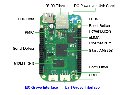
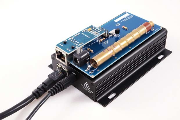
This was the known-and-tested option, so they were on hand, and were sent out in January as anticipated. The new production brought some upgrades to model A as well, including an extension port for UART, I2C and speaker as well as firmware improvements (HW version 109 and FW version 116).

KIT1

KIT1 board - top

Chinese New Year happened, and was not accounted for. This slipped up the timeline a lot, but the boards are under way now, and all the components are all available and ready. A extension header was added during the wait. It is now possible to add an BME280/BMP180 to the kit yourself. These are just the standard breakouts available from all kinds of suppliers, and could potentially use all the sensors that use this UART/I2C connection.BME280 BMP180

The PCB’s have arrived this week, so testing and assembly can start. When this goes well, they will be sent out soon. The end is near. Support for the extra sensor information is ready and will be added to the local firmware on Github soon. The hardware iteration (1.1.103) has already been added, together with pictures and instructions (see the pcb-1.1.103 folder).

The newest version has the added header, as you can see in this picture:

KIT1 extension header

Model D

Model D iterations - bottom 
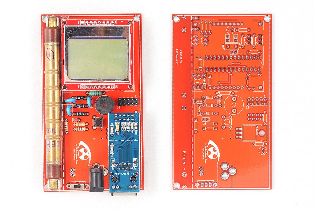
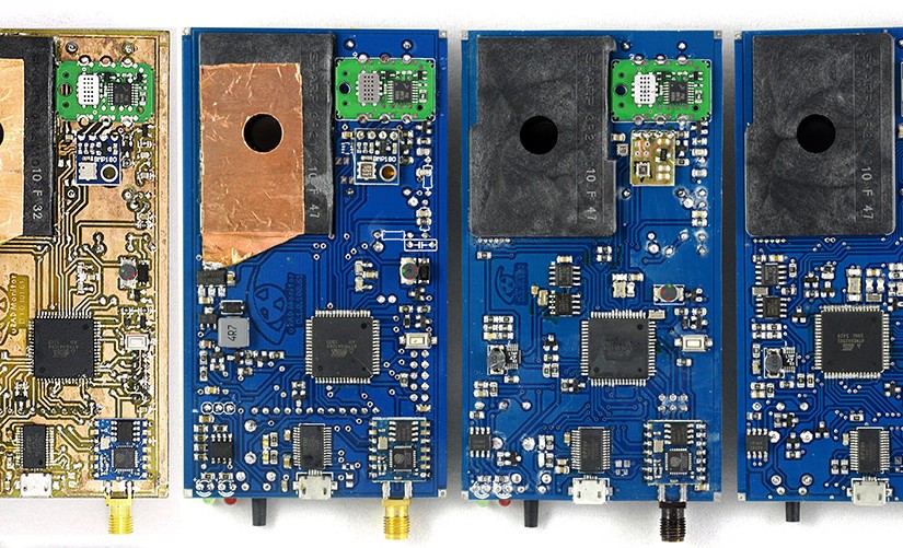
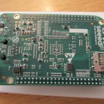
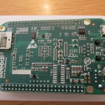
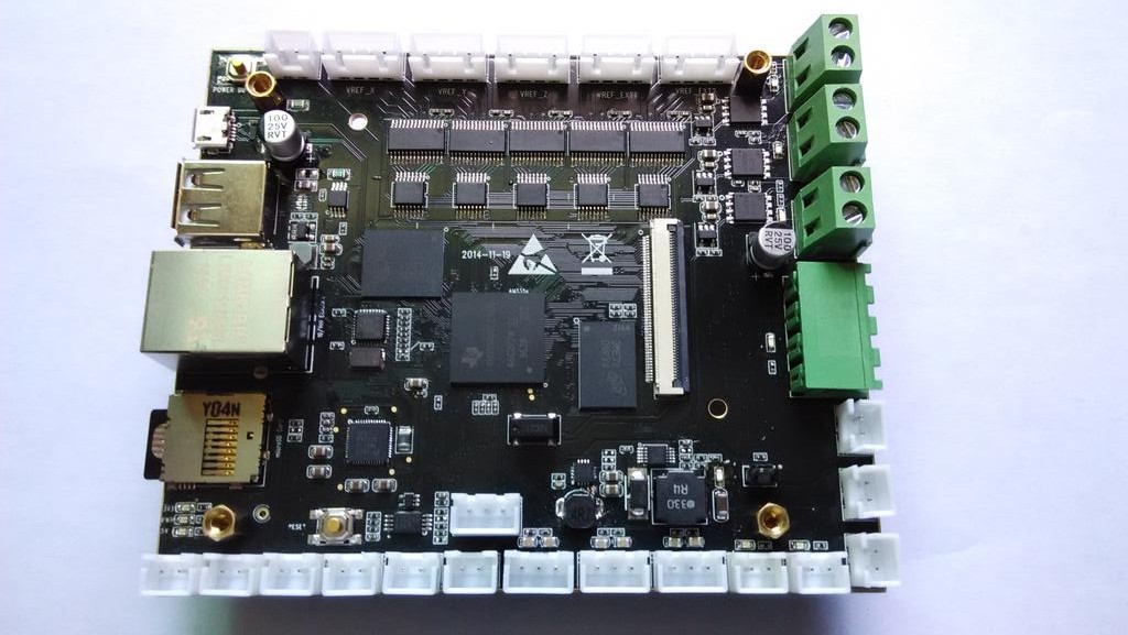
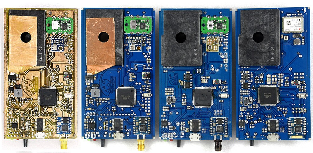
This device cost a lot of extra work, as it is a new product, and a lot of changes had to be made to make room for the stretch goals. Adding the internal antenna, GPS and SD card support added a lot of complexity to the hardware design and the firmware. This even made it necessary for an upgrade in the controller, twice. It started out with the ATMega128 in the models for the Hackaday Prize 2015, and now the ATMega 2561 is included to make room for all the hardware and firmware additions and improvements. This is also where a lot of ongoing work is done at this time, finalizing the firmware code, including the user interface. There was a total of 4 PCB iterations on making this product, as you can see in the pictures. Model D iterations - top

So at the moment the waiting game is on for the brand new BME680 sensor, when that arrives production can start. Testing and calibration would still have to be done, and this adds some time too. Things are under way, the delay is difficult, but the time is well spent adding the stretch goals to the firmware.

Radu: “Regarding the software, it really needs to be fully functional, as subsequent updates are possible, but only for those having a programmer and the right toolchain (need some technical skills to do that). There will be OTA updates somewhere in the future, but there’s still a long road to get there as it requires non-trivial implementations both in firmware and on server side.”

My projected campaign timeline

All Model A’s are sent out.
The blocker for KIT1 is the board, this should arrive this week. The design is tested, and no problems in testing are expected. If all goes as planned all KIT1 perks can be shipped this month.
The model D could take some time as not all the parts have arrived, and the firmware is still being finalized. Once the parts are complete, production should be ready in about two weeks, and testing can start. This means the Model D will take at least a month from now, and that is when all testing goes well.

Delays are common on crowdfunding projects, but can be expected. The delays are not nice, but it is good to know that Radu is doing all he can to send us the best devices possible. On the positive side, we’ll get some extra features in both hardware and software. The projected timelines in the post are mine, not his.

Can you still get a uRADMonitor now?

The initial goal is to produce 60 model D units, and only 44 are sold yet, so there is still room to get one just after the IGG units are sent out.
The Model A is still available for immediate shipping.
KIT1 is approaching the finish line, and units will also be available for immediate shipping starting April 2016.
They are still orderable at IGG, and it is always possible to send Radu an email to order them directly.

How can you help the uRADmonitor project grow?

There are a lot of things the community can do to help. The obvious would be to get a sensor, but there are other things as well.

  • Radu needs information on environment sensors that he could add to the measurement devices.
  • If you program, it would be good to see improvements to the KIT1 firmware.
  • Or if you’re in mobile apps you could help with the uRADMonitor Android app – not yet announced but apparently happening (source)
  • Are you a writer? The models could all use a nice manual.
  • If you are good at design, there could be a project designing flyers to explain what is happening when someone is using the Model D to make mobile measurements, or what the uRADmonitor project is about.
  • Are you a web designer? Then maybe there is something to help with for the frontend of www.uradmonitor.com.
  • If you are a teacher, there could be a set of instructions to teach students about the measurements that are possible, with or without the uRADmonitor devices, to keep tabs on the environment.
  • Do you like building games? Why not try to make a game using the measurements that can be done (not just how to find Chernobyl).
  • Translators, you know what can be done :)There are lots of possibilities, and Radu could use all the help he can get.

    I hope this answers most of your questions, if you have more, do not hesitate to ask him. Reach him directly on mail: Β radhoo.tech@gmail.com.

    This covers mainly what I was able to learn communicating with Radu, it is easy to like this project with all the support he offers contributors and people new to the uRADMonitor project. It is no wonder his project is already so successful.

    I’m very interested in the progress the project makes, and how big the potential benefits are going to be.

Rad1o, the CCCamp SDR badge

As a nice tradition, some events have given out badges that inspire the visitors to tinker with them, to give everybody a common thing to work on. At the CCCamp 2015 this was the Rad1o. This badge is a full Software Defined Radio on one board. As everyone present had one, the possibilities for experimentation with this advanced device were large, and there were some events that used the badge, like a beginners workshop and a foxhunt.

Picture thanks to Christoph Krichenbauer (CC BY-NC-SA)

There are a lot of things to learn with this device, from soldering the optional parts, getting a casing (thanks FablabTruck), uploading firmware, configuration, to animating and more. All that is even without using it for the SDR functions.

Once you start discovering that part of the device, things like antenna’s, frequencies, modulation and more get into view, and things get really interesting. The install of the software can sometimes be a bit tricky, but once you are set-up, lots of information is available on the web, like Michael Ossmann‘s introduction course into SDR with a very similar device. Some info from others can be found here.

Since its initial use during the CCCamp its firmware has changed a lot. The stated “current release” was still REV02 from 13th of August though, and no-one was doing an update. That is why I just uploaded a REV03 “Ketchup” version of the firmware to the wiki. It is just a build of the current GitHub with one change, the change of the REV. Here are the update instructions. As this badge will be the current CCC badge for the next four years, it could get a lot of extra features in the next years. I am very interested in seeing this firmware grow better.

I would like to do a good changelog of the changes since REV02 and have some info from the Git, but I would like your help. If you have more information about what was changed in the Rad1o FW please contact me at the “info” address on this site.

Also, if you did some cool experiments or had interesting experiences with the board, please let me know.

I personally have experimented with some antennas, and will do a writeup about this later.

BeagleBone Green Part 7: Arrival!

It is real, and it’s here. The BeagleBone Green has arrived, and it looks great! Thanks to the people at SeeedStudio I already got a preview.

It's real, and it has arrived!
It’s real, and it has arrived!

Today I got a box in the mail, and inside was the BBG:

Contents of the box
Contents of the box

The box contains a clear manual, a short USB cable, and the BBGreen board itself. It looks very clean and just as well made as the BBBlack.

They also sent me some Grove modules to start experimenting with:

Also in the gift pack, 10 Grove modules.

Here are some more pics of the unboxing, more will follow once I got more time to experiment, but first there is my B-day to take care of. πŸ™‚ Thanks for the presents!

Also I would like to congratulate the BeagleBoard.org team with the new “BeagleBone Compatible” part of the family, I hope it will grow to be used by a lot of other boards.

Go and get one for yourself here! For more info read the Wiki page, and of course all the previous posts about it on this site. Please tell me what you made with it, and be sure to post your recipe.

BeagleBone Green Part 6: Orderable Now

It finally arrived! the orderpage has more info and lists the differences between the BeagleBone Black and BeagleBone Green. It will be sold with an USB cable and a user guide. The price is indeed $39, as announced in previous posts. It’s a preorder for now, the site says: “Planned Shipment Date: Aug 20, 2015”.

They also prominently show the BeagleBone Compatible logo. I hope that program will be used by a lot of other boards. That means the official BBB images work for it, but on the wikipage there is a specialized version of the image.

BBG Overview

It was a lot of fun following the development of the device throughout this year, and I cannot wait till it arrives. Good luck and thanks to BBG and SeeedStudio! (I’m not one of the mentioned Media Highlights, but this blog is too small πŸ™‚ ) Don’t forget to order the I2C Hub as well, likely you are going to need it.

Update: Yay, I’m included in the Highlights πŸ™‚ Thanks!

BeagleBone Green Part 5: Almost there!

There is more info from SeeedStudio that the BeagleBone Green will be orderable from the 12th of August, and the price will be $39. That is a good price point if you ask me, and I hope there will be a lot of takers for it, so the Beagleboard system will grow and improve.
There also is a BBG Seeed Wikipage.

It seems on the pictures on the Seeed Promo Page that the RTC has been removed. Disappointing, but easy to work around.
The I2C hub seems to be necessary to most projects, if you’d want to avoid a full cape.

No more RTC.
No more RTC.

There is a list of supported Grove modules on the promo page, and also a all of modules from the Grove Starter Kit for Arduino are supported:

From the Starter Kit:
Grove – LCD RGB Backlight
Grove – Relay
Grove – Buzzer
Grove – Sound Sensor
Grove – Touch Sensor
Grove – Rotary Angle Sensor
Grove – Temperature Sensor
Grove – LED
Grove – Light Sensor
Grove – Button

Additional supported modules:
Grove – 3-Axis Digital Gyro
Grove – 3-Axis Digital Accelerometer 1,5g also: 16g 400g
Grove – 3-Axis Digital Compass
Grove – IMU 10DOF
Grove – Digital Light
Grove – Temperature & Humidity Pro
Grove – Barometer
Grove – Finger-clip Heart Rate
Grove – GPS
Grove – IR Distance Interrupter
More are being worked on. Also kits are in preparation to get you setup with a complete kit to start experimenting.

About BeagleBone compatibility: there is a new logo infopage on the Beagleboard.org site, explaining the new endorsement level: “BeagleBoard Compatible”. From the info: “The product bearing the BeagleBoard Compatible Logo has been tested by BeagleBoard.org and has been determined to be BeagleBoard Compatible. […] General support for this board is available from the BeagleBoard.org community. All hardware support for this product is the responsibility of the supplier. Return merchandise authorization support is provided by the supplier and access to this is provided by the supplier via its website.”

This means the BBG is the first to be on this “looser” rules that allow for hardware design changes, while still using the BeagleBone name. This is a great way to add more resources to the boards design, and the BBG is the first example.

More may follow, like the BeagleCore (Warning: annoying autoplay video), a project to make the core of the BB separately available for industrial use, much like the RaspberryPi compute module. It seems to be not reaching its goal (it runs till 7th of August, just over 10% with 3 days to go) but it could be this is just because it is aimed at the wrong audience. The board seems to be more suited to industrial designs, a hobbyist would most likely not be in the position to get this board in use without just using the BaseBoard, which makes it into a normal BBB. If you like the idea, pledge fast!

Well, for now this is all the info I got, more to follow once the board arrives πŸ™‚

The BeagleBone Green part 4: New opportunities

The new addition to the BeagleBone family – the upcoming SeeedStudio’s BeagleBone Green – has some changes, and they offer new limitations, but also new options. (for more info, read parts 1, 2 and 3)

Some of the changes are removals, like the HDMI chip and the barrel jack for 5V, and some are additions like the RTC and Grove connectors. Each change can be a plus to the user, as long as he knows what to expect.

A picture that shows off the new Grove connectors and the RTC battery holder on a proto BeagleBone Green.
A picture that shows off the new Grove connectors and the RTC battery on a proto BeagleBone Green.

HDMI support has been unimportant for a number of people who just want to setup a headless system, and do not need HDMI support at all. This frees up 20 pins, which on the BBB are also assignable to GPIO, PWM and UART ports. For people needing more of those ports, this could make it easier for them. The BeagleBone Black could also free up those ports when disabling the HDMI virtual cape in the Cape Manager, but if you do so, it is now an option to not have to worry about that at all. See http://elinux.org/Beagleboard:Cape_Expansion_Headers for more info on this.

A barrel jack for the 5V input is missing on the Green’s design, nowadays consensus seems to have set to using microUSB, so adhering to that frees up room on the board, and removes one clunky connector. The barrel was a more study design, so if you will have strong vibrations in your application, you might want to look into making extra sure the connection does not get severed.

An RTC (real time clock) is a great add-on, among others for the people using the built-in random number generator, as it gives them a good time source as well, so it could do time-sensitive encryption protocols from startup, without having to rely on unverified sources before connecting directly. There are a lot of other uses for a board that can reliably keep time even when the board is not powered, without having to rely on external sources. The space to add the battery is provided by the removal of the HDMI chip.

But a great asset will be the addition of the two Grove ports. SeeedStudio’s Grove is a system of base boards, Stems (like the BeagleBone Green) provide the processing power, and the Twig modules provide sensory input and output. There are a number of different connection types, but as there are only two of them on the board, I will concentrate on those for now.

I2C (pronounced IsquareC): This is a protocol for IC to IC communication, and it can be used my multiple modules chained together. They can be individually addressed by a hex value. There are a lot of Grove modules that can be used this way, see this list on the Seeed Wiki. A lot of the modules are IMU’s (Inertial Measurement Unit) that can sense acceleration, orientation and more. But also the small OLED screens could easily be connected to a BeagleBone Green now, for status updates, or with some buttons even a full user interface.

A small OLED screen to provide status messages that could just be plugged in into the I2C Grove connector

UART: A serial communication method, that can be used to communicate between computers, and other things like the modules listed in the Seeed Wiki. This includes things like a serial camera and wireless connection modules.

These devices can also be connected via the expansion headers on the other BeagleBone’s, but having a dedicated connector can make things a lot easier and faster to get setup.

These improvements are not earth-shattering, they are refinements that can make the BeagleBone Green a more interesting platform for builders that do not need some parts of what the Black offers, while retaining everything we have learned to love from the BeagleBone series.

The Grove line of products also offer a lot of other modules, like Analog and Digital Twig’s, and these can also be used with the BeagleBone Black as well as Green, you just need to use Grove to Male Jumper wires. These cables are also useful if you need access to more UART or I2C ports.

I am interested to see if there will also be kits to take advantage of BeagleBone Green’s advantages, but there has not been any information on that yet.

The BeagleBone Black has almost sold a quarter of a million boards, as seen in the docs, so I hope the addition of the BeagleBone Green will add even more users to this already very popular platform. I cannot wait till the release date of 19th of June!

I also want to thank the people of SeeedStudio for working with me on this series, they must grow tired of my constant questions, but try to keep me informed as best they can πŸ™‚ Keep watching this space for more info πŸ˜›

And here is Part 5!

The BeagleBone Green part 3: Presentation

So the Maker Faire Bay Area is in full swing, and info about the new BeagleBone Green is in. After 4 months and a day, the rumors about a BeagleBone Green come true. The differences with the reference BB Black design were mostly known from our previous blogposts, but there was one new thing that was not in the pictures before, and that is a builtin RTC with battery power.

The board will not be available immediately, we’ll have to wait till June 19th to order it, and it will cost about $50, which puts it in about the same price range of the BeagleBone Black. The release will be at the Maker Faire Shenzhen.

There is a video with Jason Kirdner from BeagleBoard.org, explaining about the differences between the BBB and the BB Green. He also tells some things about the other boards that have been made based on the BeagleBoard designs, that were also mentioned in my January blogpost.

See the video here:
[youtube_sc url=fxHyAgybbZs]

As soon as the people of SeeedStudio are able to send me their info, I might have more news, but it seems Jason told us most of what we can expect already. Maybe I can get some better pictures too.

I am very interested in the BeagleBone Green, but I think SeeedStudio/BeagleBoard.org could easily get more interest from the community. If there is only one marginal site that is interested in talking about a new product till the day before the presentation when one other blog finally picks it up, that shows that Open Source Hardware marketing still has a long way to go. Competitors that have less freedoms and functionality in the products themselves are much better at making a buzz for their new products.

It does however show the organic appeal that BeagleBone gathers, that without a lot of marketing, the BBB is still seen as the runner up in SBC boards, after RPi and their massive marketing push. I dont think it is their fault though, there is no good way yet to follow the progress made on OSHW that solves specific solutions, so the closed way to present new designs that is known is the only way to reasonably go.

Do not get me wrong, I love the OSHW movement, and am a happy customer of both Seeed and BeagleBoard, but I think this halfhearted approach to introducing a new product does not help OSHW. If you give out hints to the community, feed the buzz, not let it die out again.

That said, I hope to have one in my hands soon, so I can show more about the plus points of the BB/Grove combination. And again, if you know more or have made pictures of the BBG, please contact me!

Update: (2015-05-18) Some pictures emerged on twitter showing the BBG at the SeeedStudio booth:

BBG1t

BBG2t

BBG3t

We continue with part 4 of this series.

Thanks to Jason and the team at Seeed to make this great board possible! To be continued πŸ™‚

BeagleBone Green close to release

Today, on the SeeedStudio blog it shows the first picture I know of of the new BeagleBone Green they announced in a previous post, I also wrote about that discovery in my last post. After four months of suspense, the rumors come true πŸ˜›

This seems to be the new SeeedStudio BeagleBone Green.
This is the new SeeedStudio BeagleBone Green, as seen on the bottom right of the silkscreen.

The changes are (among others?) the two Grove ports. There are a UART and a I2C port, the USB-port has moved to the place of the power jack and move/removal of the HDMI chip.

The two Grove ports as seen in the picture.
The two Grove ports as seen in the main picture.

The Ethernet still is 10/100 and the SD card markings on the top-right are gone. Maybe all the BB parts are concentrated on the left, and grove on the right. Chip numbers are not visible at this images resolution, but they seem the same (probably the same chip, the TI logo can be recognised). As soon as we have a picture of the back side (or in higher resolution) we will know more πŸ™‚ Perspective seems to show it is almost flat at the back, so I don’t expect more Grove ports there.

The single USB port marked "USB Host"
The single USB port marked “USB Host, in place of the power plug. Y cable for power?”

There will be a public presentation of it soon as it is planned for a May release, but the people at SeeedStudio asked me to wait for a few days to tell you about when and where, while they gather more info. I will keep you updated, as this could be a very exiting board, dependent on the price of course. I cannot wait to see what I will able to do with it.

Probable specs:
(Mostly the same as the BeagleBone Black)
1GHz AM335* Processor
512MB RAM
4GB eMMC storage
RTC chip and Battery (Updated info)
1x MicroSD card slot
1x 10/100 Ethernet port
1x USB Host (combined with power?)
1x Grove I2C
1x Grove UART
Likely no HDMI (which i never use anyway, so that is a plus)

I hope I win the contest! I sent a comment as soon as the post came up, but I’m not approved yet. πŸ™‚ Who knows. The message was sparse, others made much better observations in their comments.

Update: The presentation of the BeagleBone Green will be at the Maker Faire Bay Area 2015 on 16-17 May, so if anybody is there, I would like to hear what you have seen! This will just be a demo, the BBG will be on sale on a (to be confirmed) later date. Cannot wait πŸ™‚

Update2: There is another blog that picked up on the BBG today, and even has some extra info: “May 15th, 2015, 9:10AM -Beagleboard.org now has a separate page for the BeagleBone Green: http://beagleboard.org/green. It points to Seeed Studio. No content uploaded yet.”

Update3: More info emerged during the Maker Faire the 16th, see the BBG blogpost part 3 πŸ™‚

And even more info in part 4.

Exiting days ahead! For those going to the Maker Faire, please keep me posted at info at ikmaak.nl with all info you have!

BeagleBone Green?

Interesting Beaglebone news: In one of SeeedStudio‘s latest blogposts by Eddie Hu about RaspberryPi alternatives there is a competitive analysis with an interesting item. There seems to be a plan within SeeedStudio to release an alternative BeagleBone with Grove sensor connectors, with the (code)name “Beaglebone Green”.

BeagleBoneGreen Announcement?

And for better visibility I will zoom in:
Zoomed-in text

The Grove line of products is a set of breakout boards with standard connectors to Analog, Digital, I2C or UART. Most of these tools are sensors and the add-on boards to Arduino, Raspberry Pi, and other small computers. Their site already lists 156 products.

Technically, one of the best boards for the purpose of using a lot of their sensors at the same time is the BeagleBone Black. Their board has specifically added things like analog i/o and real-time processors so no extra Arduino is necessary, like on the Raspberry for instance. The only problem is the intimidating expansion ports that most of the time just work as side bumpers. They do that job very well by the way πŸ™‚

The people at SeedStudio already made a Grove Cape for the BBB, but that is almost as big as the BBB itself, and seems not to adhere to the cape instructions as it has no EEPROM to provide setup info. It also has only two Analog(dual) ports, two UART ports, and two I2C ports. As most Grove sensors only use one of the analog ports, it can get full rather quickly, unless you mod the cables yourself. The digital ports are easily reachable from the GPIO itself, but that is beside the point with Grove modules. All that could be solved by a BB version with a lot of adapters built-in.

So SeeedStudio adapting a BeagleBone to become extra Grove friendly would be a huge boost to the usability for hackers prototyping new ideas with their system. Add to that the possibility that people could add a lot of tutorials to that base, moving the Grove Wiki documentation from mostly Arduino based, to BeagleBone Green based. As prices for ARM based development boards keep falling, the competition to dethrone Arduino seems to be mounting.

We asked about it on the blog yesterday, the post was moderated, but no more info was given. Maybe more will be known soon, there is a mail gone out to ask for more info.
We will also ask someone within the BeagleBone project for more info.

I could not find more info on search engines, maybe you all could do better?

I’m looking forward to it πŸ™‚

Update:(2015-01-29) I got some answers from the SeeedStudio people, they confirm they are working with TI on the a BeagleBoard Green, but haven’t got approval yet. They are sample testing now, and hope to sell the boards in May of 2015. I have asked for more info, but there was no reply yet (two weeks, so chances are low).
The people from Beagle/Circuitco haven’t replied yet (also two weeks ago) or acknowledged receipt of my mail. Maybe I should do a follow-up mail?

Update 2:(2015-02-04) I met someone from BeagleBoard.org on IRC, and he did not want to “give details they aren’t giving about their product”, but explained there are other boards in preparation based on non-BeagleBone designs, and that “BeagleBoard.org is very interested in having people clone the design and trying to help promote those clones”.

“The design is open, so ultimately they can do what they want in terms of product development. Details around branding are still being worked out.” So for now there is no decision on using the BeagleBone name on non-Beagle designs. The “BeagleBone compliant” badge would be only for direct clones, so other designs would need a different badge. For more on the organization’s view on the BeagleBone design, see the talk (video) from Jason Kirdner of BeagleBoard.org during the OHS Summit 2014 in Rome.

As an example of their cooperations he referred to the upcoming Arduino Tre a cooperation with the Arduino team that should arrive soon, and also another board that is under development, the BBP, which seems to be a BeagleBone for Reprap, designed by Truby Zong. An eventual release date is still unclear.

A view of the prototype BBP

As Truby describes it himself:
BBP BeagleBone 3D printer control board:
1GHZ AM335X
5 stepper motor drivers
3 MOSFETs for 2 extruders and 1 HPB
6 MOSFETs for Fans or LED strips
6 endstops

Also there is mention of a new board from BeagleBoard.org itself, the BeagleBone-X15 but that will be a very different design, also at a different price, certainly above $100. But also with lots of more extra’s πŸ™‚ It should arrive in the coming months.

BeagleBone-X15
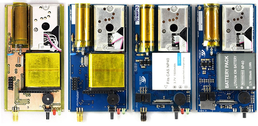
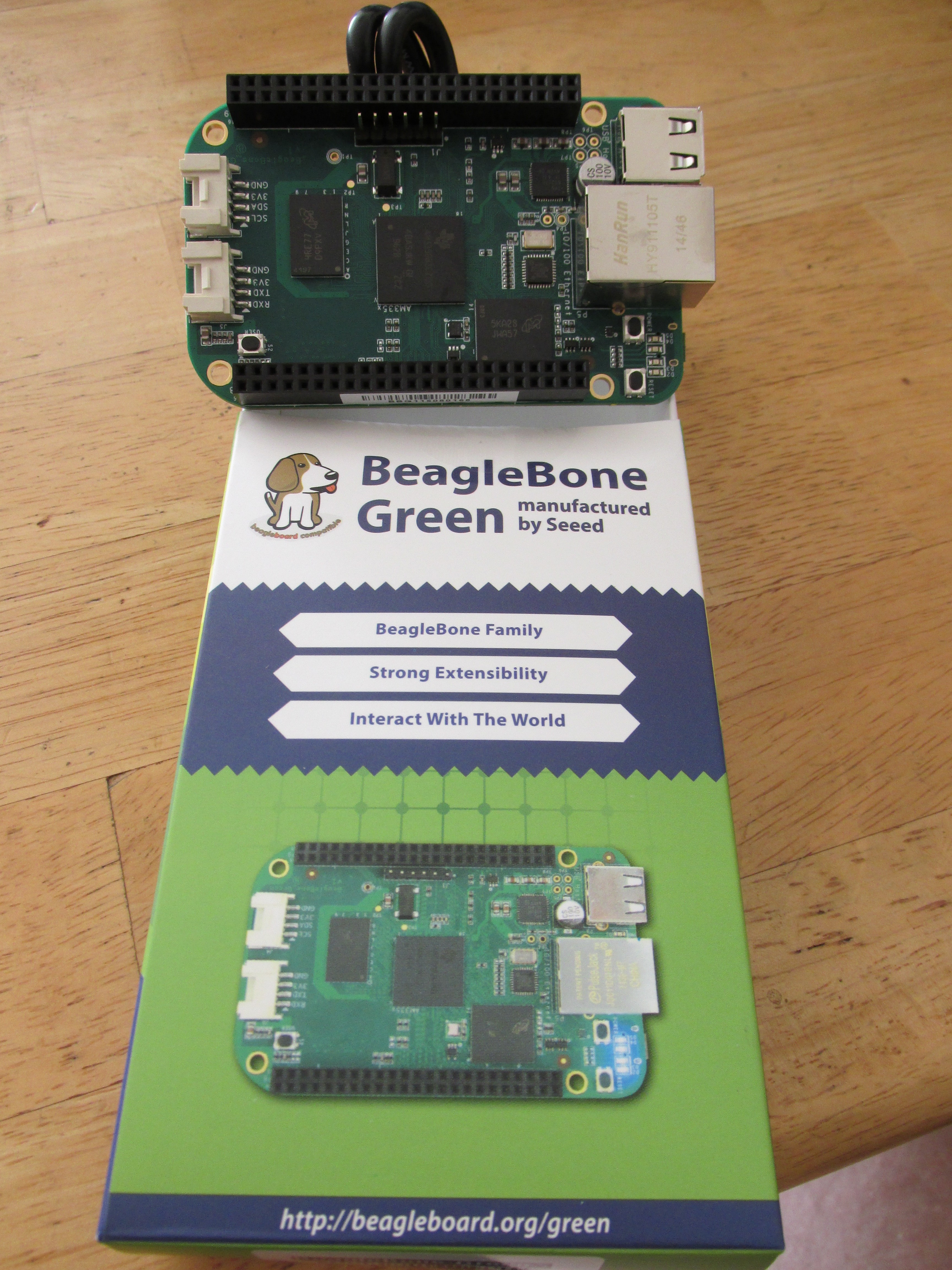
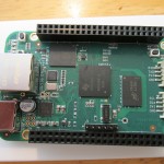
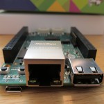
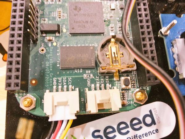
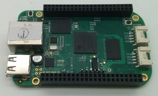
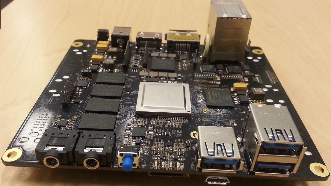
BeagleBone-X15 Beta board image.

More news when it happens. There surely is a lot happening on the BeagleBoard.org side of things. This update could have been a full post in itself!

Update 3: (2015-05-08) New blogpost with more info.

Update 4: (2015-05-16) The board is presented, see here for the info.

Update 5: The story continues in part 4.